
When writing Data Load – Turbo Integrator Processes in Planning Analytics, it is essential that effective Source and Zero-Out Views are created to ensure a correct transfer of Data. In Planning Analytics, a View is a user-defined collection of data intersections of a specified cube. The data intersections of a view are made up of subsets of all the dimensions of that cube.
Source Views are used to help us gather a group of data intersections from a sourced cube that will be used in a TI Process for data manipulation or transfer. Zero-Out Views are used to clear out a group of data intersections from a targeted cube. A user can use this to clear any old data at the group of intersections before new data is input, or simply used to just remove data from a cube.
Source and Zero-Out Views are inherently very similar, with a few small differences that make them unique. Both types of views are created in the Prolog tab of a Turbo Integrator Process. The Prolog tab allows a user to perform a series of actions before the Data Source is processed. Essentially, the Prolog Tab is a staging area before any data is moved or manipulated.
Coding for these two types of views can be categorized into four main sections:
- Variable and View Creation
- View Extract Properties
- Subset Creation
- Static, Logic Derived, MDX
- View Assign and Data Clearing
I will take you through each section one by one and offer some good tricks!
Before We Get Started:
In order to create an effective view that is easy to navigate and troubleshoot, it is paramount to use meaningful Naming Conventions. Naming Conventions can vary, but they should be consistent throughout a Planning Analytics model to avoid confusion between different TI Processes and TM1 Objects. Some good examples that can get you started are below:
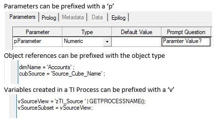
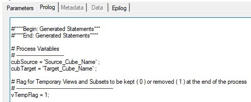
Variable and View Creation:
At the beginning of our Views we want to establish a variables section that will determine:
- Our Source Cube to grab data from
- Our Target Cube where we will clear/input data
- Our Temporary Flag Value
When creating Views and Dimension subsets, an AsTemporary argument exists in the function’s syntax that if set to 1, makes the view/subset temporary and persist only for the duration of the TI Process. Because we are creating views to just source and zero-out during this process, we want to use this argument.
Below I have used cubSource, cubTarget, and vTempFlag as the variables to represent our cubes and Temporary Flag.
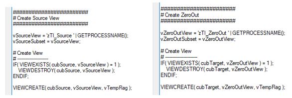
The Next Step is to create our Views. Sticking with our theme of meaningful Naming Conventions, we should create variables for our View names and Subset names, this way we can plug in the variables to the functions rather than hard-coding the names every time. vSourceView, vSourceSubset, vZeroOutView, and vZeroOutSubset are good suggestions.
As a precaution, when creating the views, we want to first check if they exist using the VIEWEXISTS function, and if so, we want to delete the view using VIEWDESTROY. Once that is done, we use a VIEWCREATE to build our new/updated view.
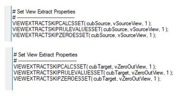
View Extract Properties:
The View Extract Properties are used to help you manage the type of data that is sourced/cleared in your view. In Source View specific terms, the below functions can help you manage the size of your source. For example, if a cube is particularly sparse, skipping zeroes can significantly cut down your source size by not including any of the data intersections with no data in them. These parameter setting may vary depending on your process requirements.
- VIEWEXTRACTSKIPCALCSSET
- Sets an option to include/exclude consolidated values in a view. 0 to include, 1 to exclude.
- VIEWEXTRACTSKIPVALUESSET
- Sets an option to include/exclude rule-calculated values in a view. 0 to include, 1 to exclude.
- VIEWEXTRACTSKIPZEROESSET
- Sets an option to include/exclude zero values in a view. 0 to include, 1 to exclude.
Subset Creation:
Now that the Views have been created and the View Extract Properties are set, it is time to build the Dimension Subsets that will make up our Views. There are three main types: Static Subsets, Logic-Derived Subsets, and MDX-Derived Subsets. All three use the same base SUBSET functions, but differ in how they insert dimension elements.
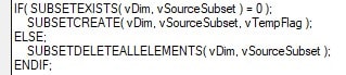
Similar to when we created the Views, we want to check if the specified subset exists in the dimension using a SUBSETEXISTS function. If not, we create it with a SUBSETCREATE, and if it does, we delete all the elements currently in the subset with SUBSETDELETEALLELEMENTS.
Next, elements from the dimension you are currently working on need to be added to the subset you just created. This is where all three Subset Types differ. All use the SUBSETELEMENTINSERT function to insert elements but use different ways to get there. Each will be covered in the next section of the article.
Once the Subset elements are inserted (Next Step), we use a VIEWSUBSETASSIGN to assign all three types of Subsets to the View we are building.
![]()
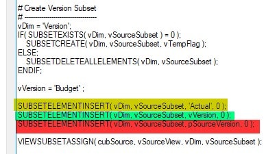
Static Subset
Static Subsets are the simply a list of elements that are input into the subset that never change. The Element names can be hardcoded (yellow), referenced by a variable (green), or can reference a parameter from the Parameter Tab (red).
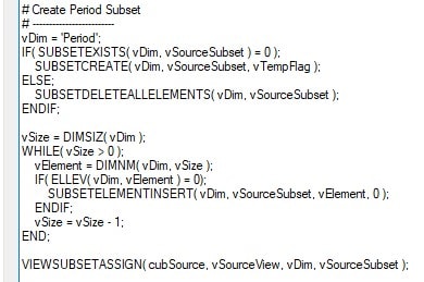
Logic-Derived (WHILE Loop) Subset
Logic Driven Subsets typically use WHILE Loops and/or some sort of Logic to determine which elements should be entered into a Subset and which should not.
WHILE loops start with a vSize variable that uses a DIMSIZ function to look up the size/number of elements in a dimension. The WHILE Loop is used to loop through all the elements in a dimension using each element’s index from the biggest index (last element) to 0, or vice versa. The vElement variable looks up the element name at the current index, and then is used in the Logic to determine whether or not to insert it into the dimension.
The below Logic loops through the ‘Period’ dimension and only adds the element to the subset if it is 0 Level Element.
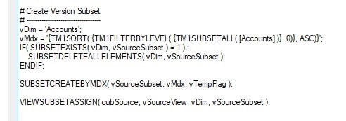
MDX Subset
The last subset type uses MDX to derive which elements should be inserted into the subset. Create a vMdx variable to define MDX code using the SUBSETCREATEBYMDX function. Note: It is important to first check in Planning Analytics subset editor that the MDX is working.
Important Subset Note: If your prolog does not contain code to create a view specific subset, the TI Process will default that dimension’s subset to ALL. For example, if there are 5 dimensions in a cube, and you know that for three of the dimensions you want to Source or Clear out all of the elements, you do not need to include any of the above code for those three dimensions.
View Assign and Data Clearing
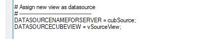
After building our subsets for both views, the last step in creating Source and ZeroOut Views are assigning the View as Datasource and Clearing the data.
For Source Views we use two functions to assign the view as a Data Source. DATASOURCENAMEFORSERVER sets the name of the data source used by the server when executing the process. In the case below, we are sourcing from the cubSource we defined earlier in the process. DATASOURCECUBEVIEW officially sets the Source View we just built as the Data Source.
We use the VIEWZEROOUT function to clear all data intersections that are in the ZeroOut View just created.
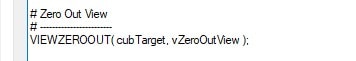
When the above Prolog runs, the target intersection of data will be cleared out, and the source view will be ready for processing by the META and DATA tabs or the TI Process.